
Fusion 360 G-Code Optimization: Eliminate CNC Chatter & Jerk with G02/G03 Arcs
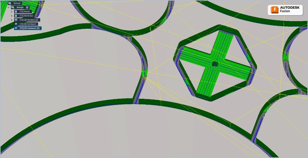
When CNC milling complex curves, round tabletops, organic profiles, or vector splines imported from CAD tools like Rhino or Illustrator, machinists and CNC programmers often face the same mechanical nightmare:
- Degraded edge surface quality: vertical striations, visible polygonal facets, micro-stepping marks, and chatter.
- Severe mechanical resonance: the gantry shakes violently, stepper or servo motors produce a harsh stuttering whine, and machine vibrations peak in sharp corners.
- Astronomical file sizes: 40,000 to 60,000 lines of code for basic 2D parts, choking CNC controller buffers.
At Alcyde, our precision CNC machining workshop near Toulouse, France, we tackled this issue head-on during a high-volume manufacturing run of 15 mm high-density recycled plastic tabletops (PAV2 panels by Le Pavé for French designer Chloé Pélissier).
This technical case study breaks down the root causes inside Autodesk Fusion 360, provides the exact CAM configuration to enforce true circular arc generation (G02 and G03), and highlights our verified workshop results: a 20x G-code file reduction and a mirror-like, chatter-free edge finish.
1. Why Do CNC Routers Jerk and Stutter in Curves?
To understand why CNC gantries shudder on curved paths, we have to examine how CAM post-processors translate geometric curves into machine language.
In the standard ISO G-code specification:
G01dictates a linear, straight-line feed move at a specified cutting rate (F).G02(clockwise) andG03(counter-clockwise) dictate a true, continuous circular arc computed from radius or center offsets (I,J).
When a curve or spline is improperly configured in Fusion 360 CAM, the software fails to output circular arcs. Instead, it discretizes the entire curve into thousands of tiny straight G01 lines, each measuring merely 0.2 mm to 1.0 mm in length.
On the machine floor, the CNC motion planner must process this blizzard of micro-segments. Even with advanced look-ahead algorithms and trajectory smoothing, the machine undergoes non-stop micro-decelerations and re-accelerations. These shock pulses trigger structural resonance throughout the gantry and spindle carriage, transferring chatter straight into the carbide end mill.
2. The 3 Root Causes Identified in Autodesk Fusion 360
Following extensive workshop benchmarking and byte-level G-code parsing, we isolated the three CAM settings that choke Fusion 360’s arc-fitting engine:
Root Cause #1: "Feed Optimization" (The Arc Killer)
Located under the Passes tab in 2D Contour operations, Fusion 360 features a Feed Optimization checkbox intended to slow down the tool in tight corners.
- The Trap: When enabled on spline contours, Fusion evaluates the transition between every single micro-facet as a potential corner.
- The Mathematical Clash: In standard G-code, a
G02/G03arc must maintain a single, constant feedrate throughout its arc span. To vary the feedrate every millimeter (e.g., oscillating between 2,700 mm/min and 1,500 mm/min over 4,200 times in our benchmark file), Fusion is mathematically compelled to destroy the circular arcs and replace them with linearizedG01vectors. - The Workshop Rule: For contouring plywood, solid wood, plastics (PEHD, POM), and composites, always keep Feed Optimization disabled.
Root Cause #2: Imbalanced Tolerance vs. Smoothing Ratio
Two core settings control the mathematical fidelity of a toolpath:
- Tolerance: the maximum permissible deviation between the idealized CAD model and the computed CAM centerline.
- Smoothing: the arc-fitting filter that condenses micro-lines into smooth circular arcs.
- The Trap: Programmers frequently set an ultra-tight calculation tolerance (e.g., 0.005 mm or 0.01 mm) while leaving Smoothing turned off or set to the same value.
- The Autodesk Golden Rule: To allow the arc-fitting algorithm to substitute a string of chordal lines with a true circular arc without violating geometric boundaries, it requires mathematical leeway. The Smoothing Tolerance must be 2 to 3 times larger than the Calculation Tolerance.
- Alcyde's Calibrated Values:
- Tolerance = 0.02 mm (more than sufficient precision for industrial joinery, plastics, and sheet goods).
- Smoothing Tolerance = 0.05 mm (provides the 50-micron envelope needed to merge chordal segments into true
G02/G03arcs).
Root Cause #3: Vertical Lead-In Vectors and 360° Closed Loops
Linking parameters directly dictate whether a clean arc can be initiated:
- Vertical Lead-In Vectors: If Vertical Lead-In Radius is greater than 0, Fusion produces a 3D helical or ramping lead-in move. Because standard 3-axis CNC controllers process arcs exclusively in the horizontal XY plane (
G17), the post-processor immediately linearizes the entire transition intoG01lines. - 360° Closed Loops: On closed circular cutouts without a tangential lead-in, the start and end points overlap abruptly without an inflection point. Fusion’s arc-fitting routine frequently aborts, generating over 680
G01lines for a simple 380 mm circle!
3. Official Workshop Settings for Autodesk Fusion 360
Apply the following parameters inside your Fusion 360 2D Contour operations for optimal results:
Passes Tab
| Parameter | Recommended Value | Technical Function |
|---|---|---|
| Tolerance | 0.02 mm |
Nominal part accuracy |
| Smoothing | CHECKED | Engages the mathematical Arc Fitting engine |
| Smoothing Tolerance | 0.05 mm |
2.5x mathematical leeway to construct circular arcs |
| Feed Optimization | UNCHECKED | Eliminates erratic feed jumps and preserves continuous arcs |
| Finishing Feedrate | Locked / Consistent | Ensures steady chip load without abrupt speed changes |
Linking Tab
| Parameter | Recommended Value | Technical Function |
|---|---|---|
| Lead-In (Entry) | CHECKED | Enforces progressive tool entry outside the workpiece |
| Horizontal Lead-In Radius | 3.00 mm |
Clean tangential arc in the XY plane (pure G02/G03) |
| Lead-In Sweep Angle | 90.00 deg |
Ideal orthogonal tangential blend |
| Linear Lead-In Distance | 0.600 mm |
Linear run-up for cutter radius compensation (G41/G42) |
| Vertical Lead-In Radius | 0.00 mm (Zero) |
CRITICAL: Prevents 3D Z linearization into G01 micro-vectors |
| Lead-Out (Exit) | CHECKED | Prevents dwell marks and cutter gouging on tool retraction |
| Same as Lead-In | CHECKED | Ensures symmetrical engagement and disengagement |
4. Machine Strategy: Modulating Toolpath Depth by Machine Rigidity
Machine kinematics dictate how cutting forces translate into surface quality:
On Modular Gantry Routers
On lighter modular gantries, radial rigidity requires a disciplined strategy. Taking the final cut in a single full pass causes tool and Z-axis deflection, inducing micro-vibrations even with optimal G-code.
- The Two-Stage Machining Rule:
- Roughing Passes: Step down in 4 to 5 mm Z-increments leaving a radial Stock to Leave of 0.35 mm (axial Stock to Leave Z = 0).
- Dedicated Finishing Pass: Using the same solid carbide end mill, plunge to full cutting depth in a single continuous pass skimming the remaining 0.35 mm with arc smoothing engaged. Cutting resistance is negligible (< 2 N): zero deflection, zero chatter, and a glassy edge finish.
On Heavy Industrial CNC Machining Centers (4x2 m Rigid Bed)
On a heavy structural steel frame of several tons, machine rigidity unlocks advanced trajectory planning:
- High Precision / SGI Mode (
useSmoothing): set toFine VelocityorAutomatic. - Machining Condition (
precisionLevel): configured toP2 More Arcs. - The post-processor outputs high-precision dynamic interpolation blocks, synchronizing industrial look-ahead pathing with circular arcs to sustain maximum feed velocity through tight curves without decelerating through contours.
5. Measured Workshop Benchmark (Customer Case Study: Chloé Pélissier)
Measured on a series of 15 mm recycled plastic tabletops with complex curved and circular profiles:
| Benchmark Metric | Prior to Optimization | Optimized Alcyde Toolpath | Verified Gain |
|---|---|---|---|
| Total G-Code Lines | 46,380 lines | 2,271 lines | -95.1% (20x file reduction) |
| Program File Size | 1,065 KB (1.06 MB) | 54 KB | Ultra-lightweight, instant buffer loading |
| True Circular Arcs (G2/G3) | Fragmented / Near zero | 803 continuous arcs | Smooth continuous motion |
| 380 mm Circle (Part 1) | 688 faceted G01 lines |
5 continuous G03 arcs |
-99.3% lines on profile |
| Feedrate Stability (F) | 4,220 erratic feed drops | 2,700 mm/min locked | Zero resonance, mirror edge finish |
Conclusion: Precision Manufacturing Starts in the Code
In modern industrial CNC subcontracting, workpiece quality does not solely rely on the cutter or machine frame. It is governed upstream by the mathematical rigor of CAM programming.
By eliminating micro-jerks and producing native circular motion, you protect your machine mechanics, multiply cutting tool life, and deliver flawless edge finishes that eliminate manual sanding.
Have a complex CNC machining project in wood, plywood, or technical plastics in France or across Europe?
Partner with Alcyde: we audit your 3D CAD files and deliver industrial precision at scale.
Besoin d'un partenaire d'usinage CNC grand format ?
Notre atelier à Toulouse et Lombez transforme vos fichiers 2D/3D en pièces usinées avec devis garanti sous 48h.
Découvrir notre service d'usinage CNC Toulouse →Need a Similar Technical Part?
Our workshop in Toulouse shapes your prototypes and medium-series wooden and composite parts with the same rigorous industrial precision.